How to Keep Great AV Documentation To Save You Money
Published September 28, 2022
Your audiovisual system should have up-to-date documentation. The reason why? It saves you money! If an issues arises with your system, knowing the exact signal flow of a system allows your service technician to troubleshoot faster. Faster troubleshooting means less cost-to-resolution, more system uptime, and ultimately more productivity for your team.
However, all those lines and boxes crossing over each other across multiple pages can be confusing. And contacting your audiovisual integrator if you make a small change yourself can be laborious for everyone. So how do you read and efficiently document any changes to your system?
As a working end user, this blog will help you to read your audiovisual documentation and easily markup simple changes using redlines.
Reading Audiovisual Documentation
During the construction phase, AV integrators work side by side with other trades in both new builds and renovations. Therefore, typical audiovisual drawings follow a similar format to other construction drawings. If you’ve never seen these types of drawings before, don’t worry. The following sections will walk through a sample drawing set from one of our old project so you can see what it contains.
Title and Content Pages
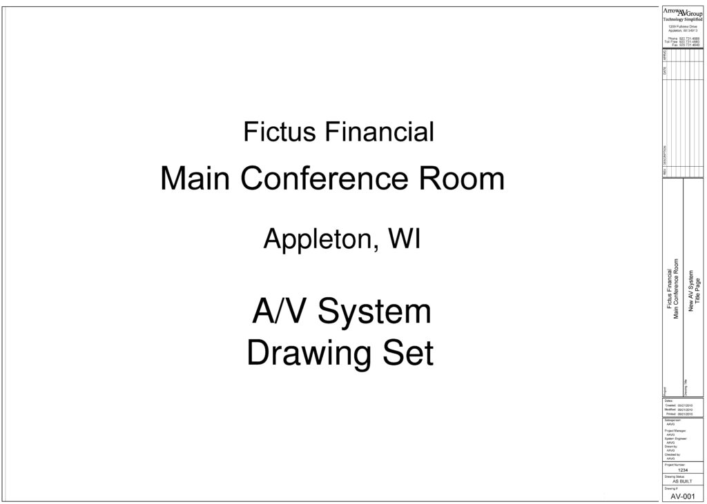
On the first page, you will find the title page, giving you a overview of what you project these drawings are for. On the right hand side, you’ll notice a large info tab. You will see this repeated on each page so you can easily navigate to what you’re looking for, see who was working on the drawings, and other notes. The title page will be followed by a drawing index and symbols key. The drawing index is just the table of contents, laying out each page within the drawing set. The symbol key describes what each symbol you’ll see further on in the drawings means.
Construction Standards
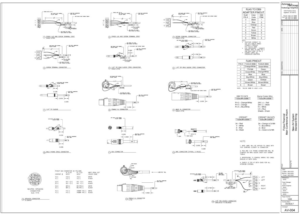
The next few pages will contain construction standards. For this project, we included standard wiring for all any possible connectors that may be in the project, from audio and video to network. For more recent projects, we also include mounting information for displays, ADA information for operation in rack, and more in this section.
Device Locations, Reflected Ceiling, and Elevation Drawings
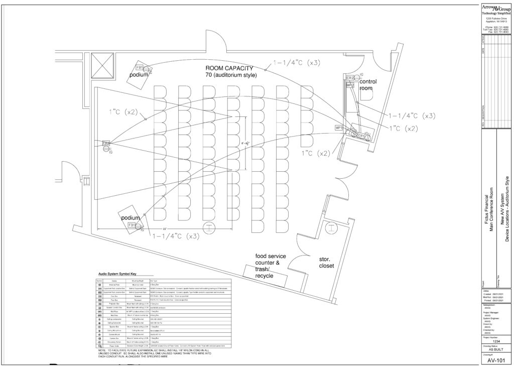
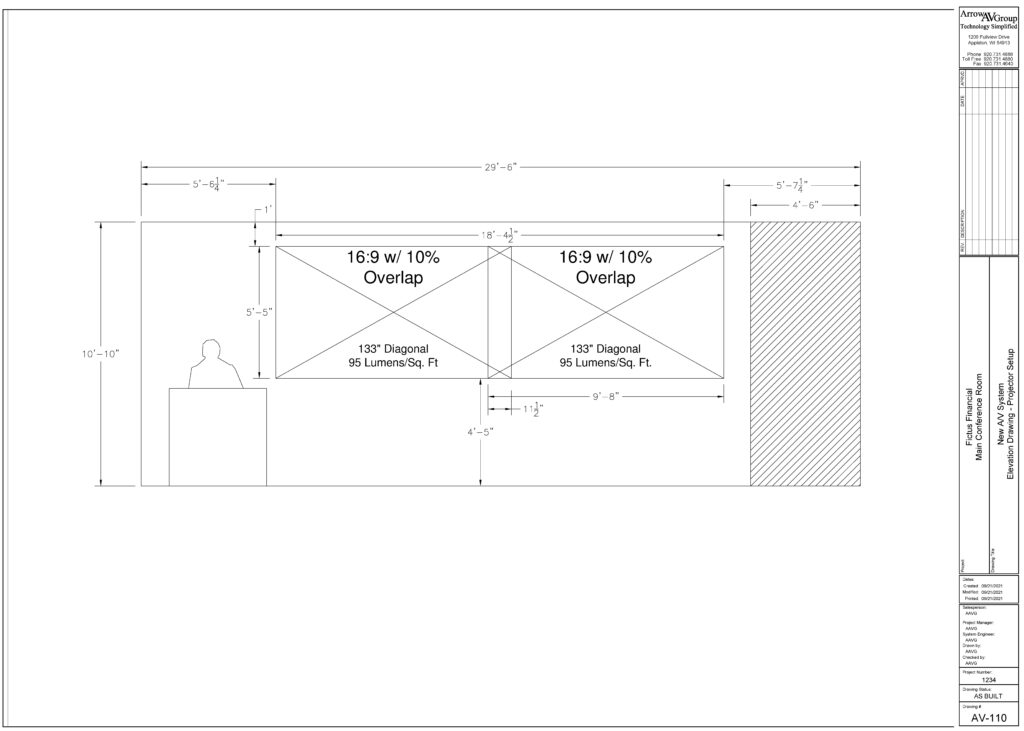
Next, depending on the complexity of your system, you might find various architectural blueprints. Reflected ceiling plan will show all trades devices in the ceiling such as speakers, projectors, lighting, emergency systems, and more. An elevation drawing will show the heights of devices above the finished floor, such as direct view LED walls or acoustical treatment.
Elevation Drawings
Line Diagrams
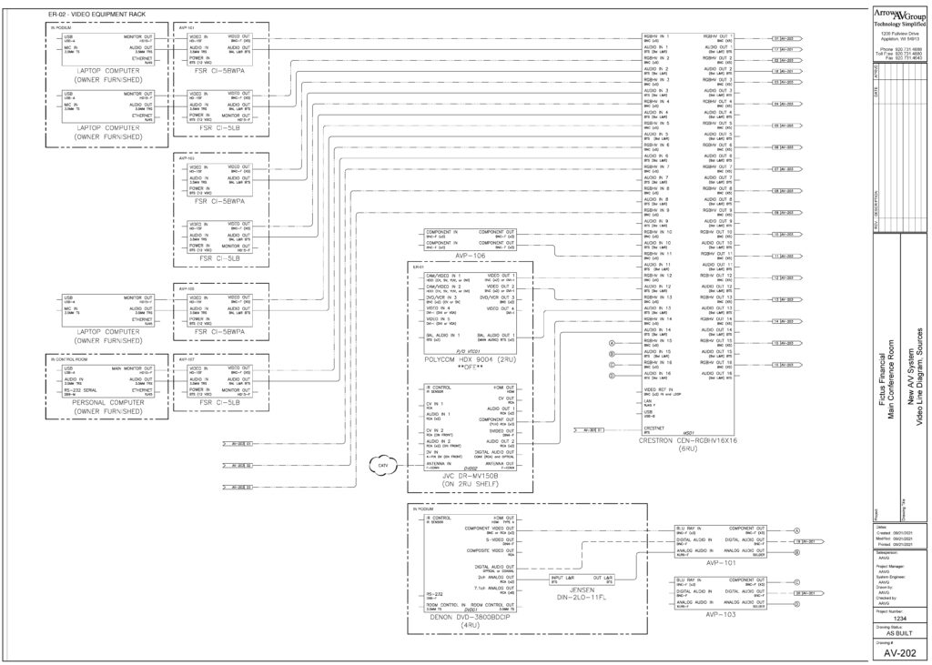
Next you’ll see line drawings of your system. These show all the connections made between devices. Signal flows from left to right, input to output. So on the left hand side, you’ll find input devices such as microphones and cameras. On the right hand side, you’ll find output devices such as displays and projectors. In between, you’ll find controllers, mixers, and other processing equipment.
Rack Elevations
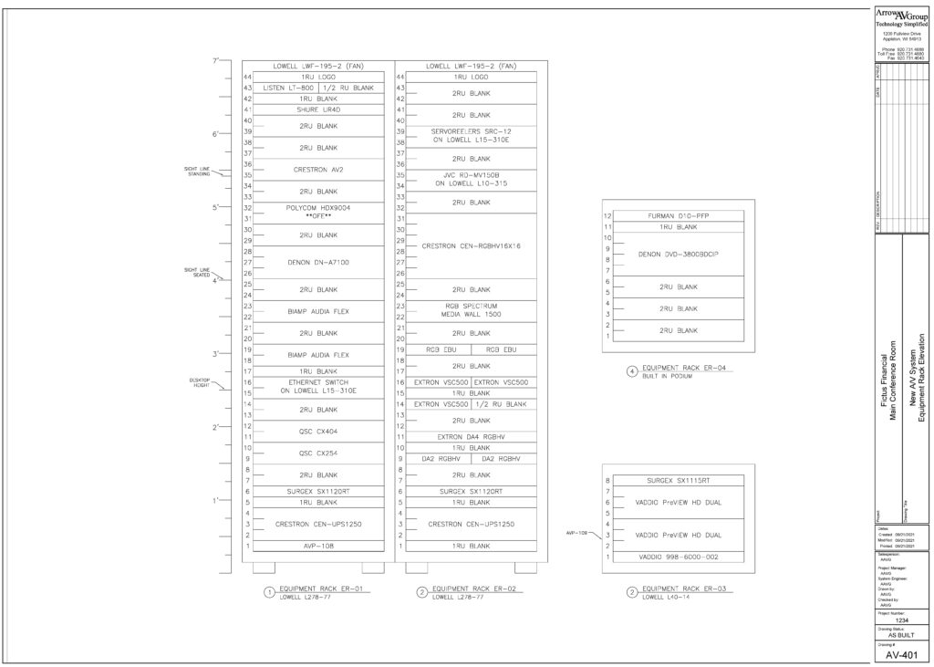
Next, if your system has one, you’ll see the layout of the rack. This could range from a small portable rack with four rack units all the way to a rack with 48 rack units which might be for a server headend. Either way, this will show where equipment is mounted and any other notes. Generally, you’ll find heavier equipment such as amplifiers and UPS’ near the bottom and equipment needing better line of site such as wireless microphones near the top.
Plate Drawings
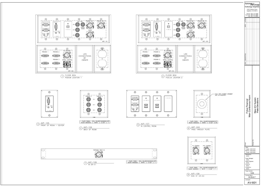
Finally, any wall plates for connecting devices will be shown at the end. This ranges from off-the-shelf HDMI transmitters to fully customized wall boxes with every connection under the sun.
Redlining Your Drawings
Now that you know how to read your drawings, let’s examine a tried and true method for updating your drawings on the fly: redlining. Redlining is the process of making additions or subtractions from drawings after they’ve been finalized. Traditionally this was done on paper using a red pen (thus the name). At Arrow AV Group, we deliver system documentation upon project completion in digital PDF format. This saves paper and reduces storage needs for clients.
We recommend using the free PDF software Adobe Acrobat for reading and making basic redlines. The free version allows for commenting and basic drawing on PDF documents.
So let’s actually redline some drawings! Check out the video below and scrub to 4:00 to get started.
Redlines start to get cluttered if you make too many, your AV integrator can implement your redlines permanently into the digital drawings as part of a maintenance plan. We recommend batch processing redlines on an annual basis to help reduce costs.
—
There you have it! Now you know how to read AV drawings and redline if you need to. If you don’t have any drawings or want to work with an integrator who values quality control processes, give us a call or send us a message to get started.
Get Expert AV Assistance
Latest Blogs
About Arrow AV Group
We are a premiere audiovisual integration firm serving corporate, government, healthcare, house of worship, and education markets with easy-to-use solutions that drive success. Family-owned and operated from Appleton, WI for over 35 years.

